
Especially if you want it to work.
There’s an old electronics joke that if you want to build an oscillator, you should try building an amplifier. One of the fundamental criteria for oscillation is the presence of signal gain; without it, any oscillation is bound to decay, just like a swing that’s no longer being pushed must eventually come to a stop.
In reality, circuits with gain can occasionally oscillate by accident, but it’s rather difficult to build a good analog oscillator from scratch. The most common category of oscillators you can find on the internet are circuits that simply don’t work. This is followed by approaches that require exotic components, such as center-tapped inductors or incandescent lightbulbs. The final group are the layouts you can copy, but probably won’t be able to explain to a friend who doesn’t have an EE degree.
In today’s article, I wanted to approach the problem in a different way. I’ll assume that you’re up-to-date on some of the key lessons from earlier articles: that you can tell the difference between voltage and current, have a basic grasp of transistors, and know what happens when a capacitor is charged through a resistor. With this in mind, let’s try to construct an oscillator that’s easy to understand, runs well, and has a predictable operating frequency. Further, let’s do it without peeking at someone else’s homework.
The simplest form of an oscillator is a device that uses negative feedback to cycle back and forth between two unstable states. To illustrate, think of a machine equipped with a light sensor and a robotic arm. In the dark, the machine is compelled to stroll over to the wall switch and flip it on. If it detects light, another part of its programming takes over and toggles the switch off. The machine is doomed to an endless cycle of switch-flipping at a frequency dictated by how quickly it can process information and react.
At first blush, we should be able to replicate this operating principle with a single n-channel MOSFET. After all, a transistor can be used as an electronically-operated switch:
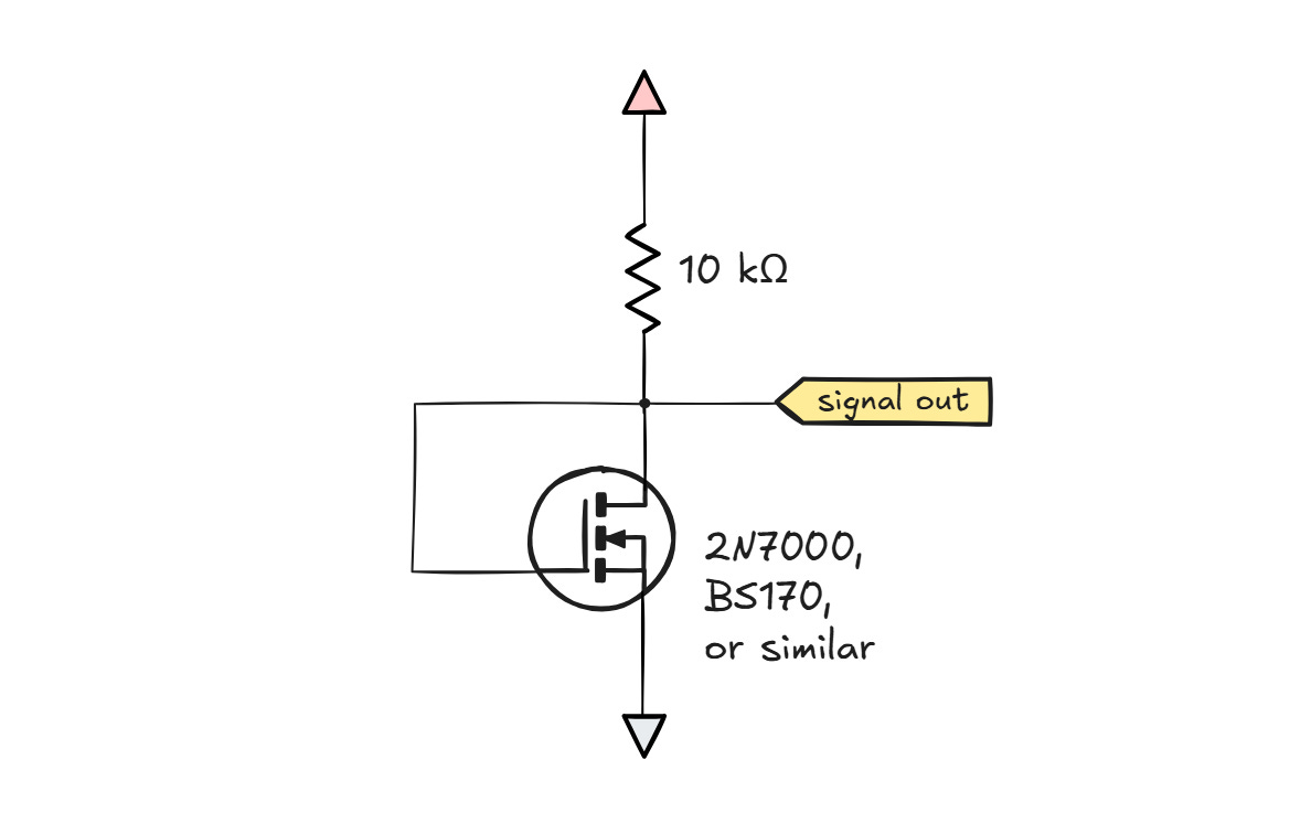
The transistor turns on when the voltage between its gate terminal and the source leg (Vgs) exceeds a certain threshold, usually around 2 V. When the power supply first ramps up, the transistor is not conducting. With no current flowing through, there’s no voltage drop across the resistor, so Vgs is pulled toward the positive supply rail. Once this voltage crosses about 2 V, the transistor begins to admit current. It stands to reason that the process shorts the bottom terminal of the resistor to the ground and causes Vgs will plunge to 0 V. If so, that would restart the cycle and produce a square wave on the output leg.
In practice, this is not the behavior you’ll see. For a MOSFET, the relationship between Vgs and the admitted current (Id) is steep, but the device is not a binary switch:
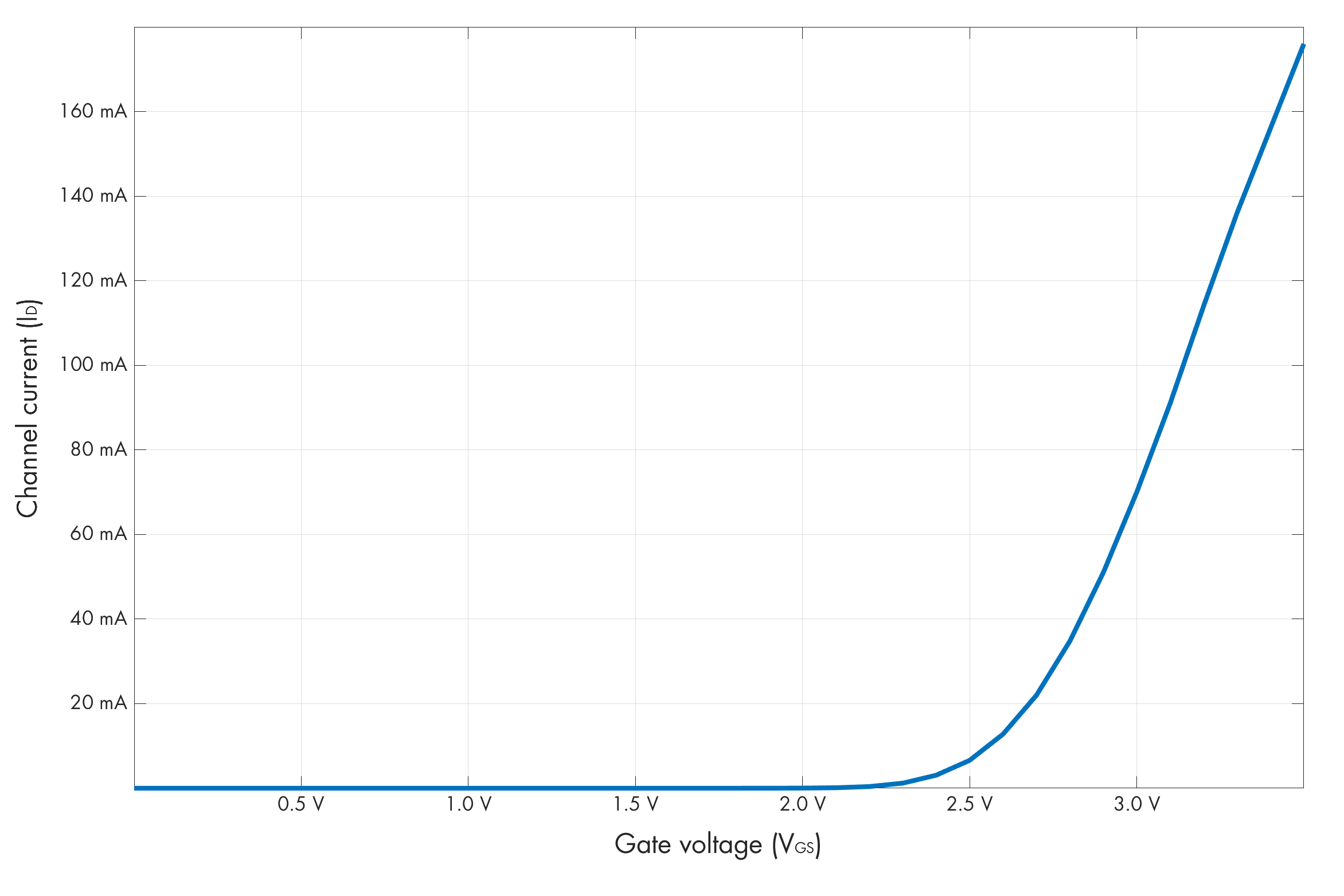
In particular, there is a certain point on that curve, somewhere in the vicinity of 2 V, that corresponds to the transistor only admitting a current of about 200 µA. From Ohm’s law, this current flowing through a 10 kΩ resistor will produce a voltage drop of 3 V. In a 5 V circuit, this puts Vgs at 5 V - 3 V = 2 V. In other words, there exists a stable equilibrium that prevents oscillation. It’s akin to our robot-operated light switch being half-on.
To fix this issue, we need to build an electronic switch that has no stable midpoint. This is known as Schmitt trigger and its simple implementation is shown below:

To analyze the design, let’s assume the circuit is running off Vsupply = 5 V. If the input signal is 0 V, the transistor on the left is not conducting, which pulls Vgs for the other MOSFET all the way to 5 V. That input allows nearly arbitrary currents to flow through the right branch of the circuit, making that current path more or less equivalent to a two-resistor a voltage divider. We can calculate the midpoint voltage of the divider:
This voltage is also propagated the source terminal of the input transistor on the left. The actual Vth for the BS170 transistors in my possession is about 2.15 V, so for the input-side transistor to turn on, the supplied signal will need to exceed Vs + Vth ≈ 2.6 V in reference to the ground. When that happens, a large voltage drop appears across R1, reducing the Vgs of the output-side transistor below the threshold of conduction, and choking off the current in the right branch.
At this point, there’s still current flowing through the common resistor on the bottom, but it’s now increasingly sourced via the left branch. The left branch forms a new voltage divider; because R1 has a higher resistance than R2, Vs is gradually reduced, effectively bumping up Vgs for the left transistor and thus knocking it more firmly into conduction even if the input voltage remains constant. This is a positive feedback that gives the circuit no option to linger in a half-on state.
Once the transition is complete, the voltage drop across the bottom resistor is down from 450 mV to about 50 mV. This means that although the left transistor first turned on when the input signal crossed 2.6 V in reference to the ground, it will not turn off until the voltage drops all the way to 2.2 V — a 400 mV gap.
This circuit lets us build what’s known as a relaxation oscillator. To do so, we only need to make two small tweaks. First, we need to loop an inverted output signal back onto the input; the most intuitive way of doing this is to add another transistor in a switch-like configuration similar to the failed design of a single-transistor oscillator mentioned earlier on. This building block, marked on the left, outputs Vsupply when the signal routed to the gate terminal is 0 V, and produces roughly 0 V when the input is near Vsupply:
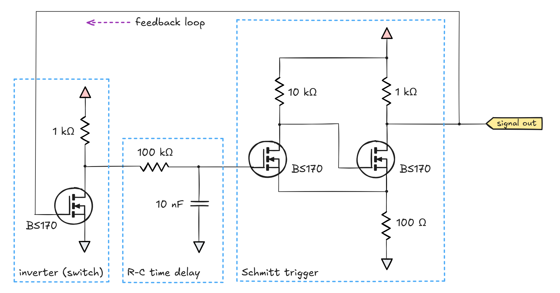
Next, to set a sensible oscillation speed, we need to add a time delay, which can be accomplished by charging a capacitor through a resistor (middle section). The resistor needs to be large enough not to overload the inverter stage.
For the component values shown in the schematic, the circuit should oscillate at a frequency of almost exactly 3 kHz when supplied with 5 V:
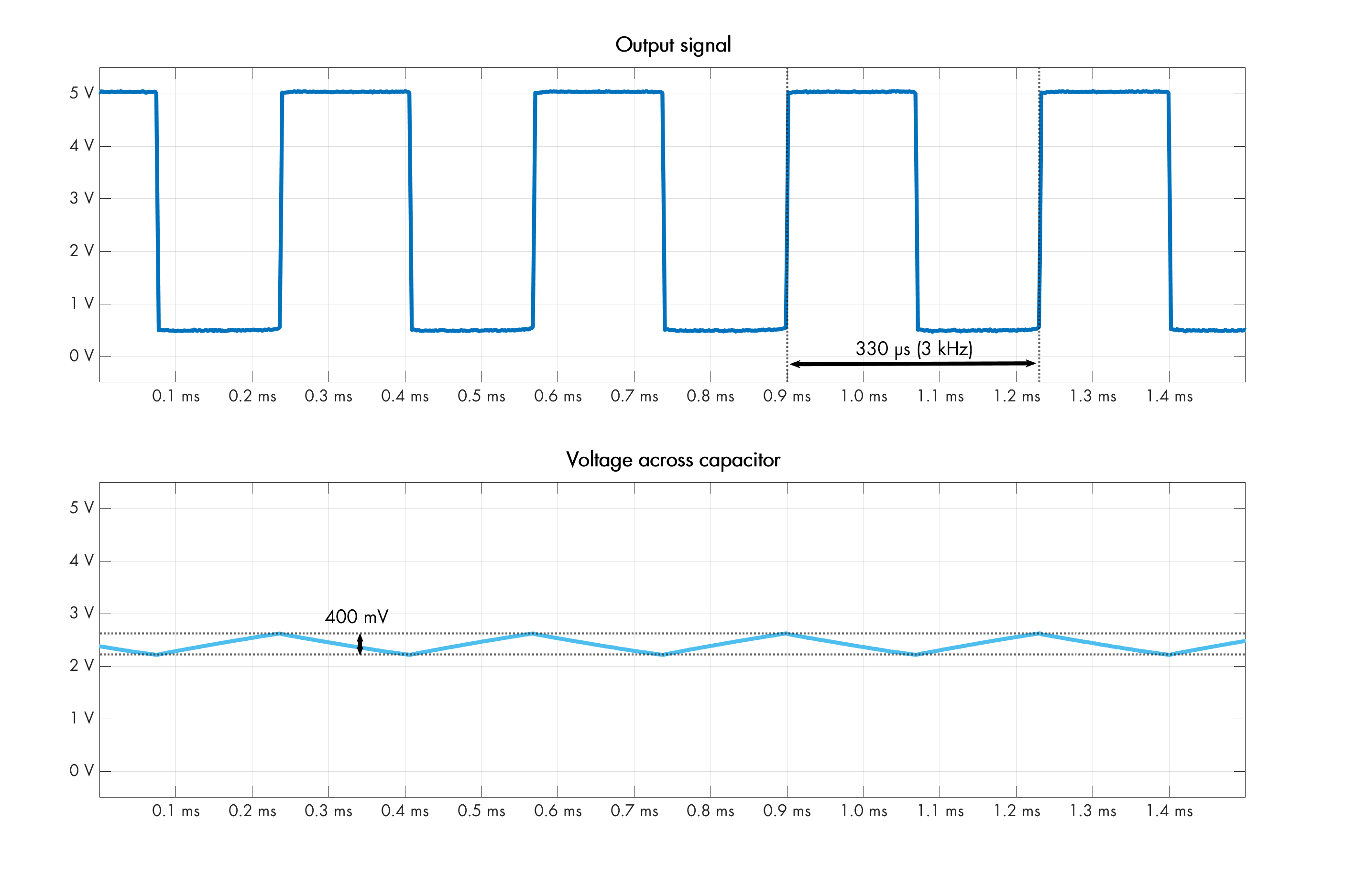
The frequency is governed by how long it takes for the capacitor to move Δv = 400 mV between the two Schmitt thresholds voltages: the “off” point at 2.2 V and the “on” point at 2.6 V.
Because the overall variation in capacitor voltage is small, the we can squint our eyes and say that the voltage across the 100 kΩ resistor is nearly constant in every charge cycle. When the resistor is connected to the positive rail, VR ≈ 5 V – 2.4 V ≈ 2.6 V. Conversely, when the resistor is connected to the ground, we get VR ≈ 2.4 V. If the voltages across the resistor are nearly constant, so are the resulting capacitor currents:
From the fundamental capacitor equation (Δv = I · t/C), we can solve for the charging time needed to move the voltage by Δv = 400 mV; the result is about 154 µs for the charging period and 167 µs for the discharging period. The sum is 321 µs, corresponding to a frequency of about 3.1 kHz – pretty close to real life.
The circuit can be simplified to two transistors at the expense of readability, but if you need an analog oscillator with a lower component count, an operational amplifier is your best bet.
If you’re rusty on op-amps, I suggest pausing to review the article linked in the preceding paragraph. That said, to understand the next circuit, all you need to know is that an op-amp compares two input voltages and that Vout swings toward the positive rail if Vin+ ≫ Vin- or toward the negative rail if Vin+ ≪ Vin-.
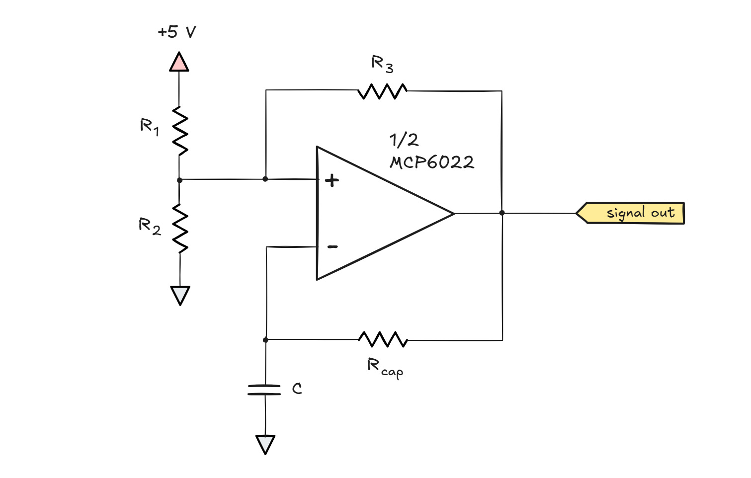
For simplicity, let’s choose R1 = R2 = R3 and then look at the non-inverting (Vin+) input of the chip. What we have here is a three-way voltage divider: the signal on the non-inverting input is simple average of three voltages: Vsupply (5 V), ground (0 V), and Vout. We don’t know the value of Vout just yet, but it can only vary from 0 V to Vsupply, so the Vin+ signal will always stay between ⅓ · Vsupply and ⅔ · Vsupply.
Next, let’s have a look at the inverting input (Vin-). When the circuit is first powered on, the capacitor C isn’t charged, so Vin- sits at 0 V. Since the voltage on the non-inverting input can’t be lower than ⅓ · Vsupply, this means that on power-on, Vin+ ≫ Vin-, sending the output voltage toward the positive rail. When Vout shoots up, it also bumps the Vin+ average to ⅔ · Vsupply.
Because Vout is now high, this starts the process of charging the capacitor through the bottom resistor (Rcap). After a while, the capacitor voltage is bound to exceed ⅔ · Vsupply. The capacitor voltage is also hooked up to the amplifier’s inverting input, and at that point, Vin- begins to exceeds Vin+, nudging the output voltage lower. Stable equilibrium is not possible because this output voltage drop is immediately reflected in the three-way average present on the Vin+ leg, pulling it down and causing the difference between Vin- and Vin+ to widen. This positive feedback loop puts the amplifier firmly into the Vin+ ≪ Vin- territory.
At that point, Vout must drop to 0 V, thus lowering the voltage on the non-inverting leg to ⅓ · Vsupply. With Vout low, the capacitor starts discharging through Rcap, but it needs to travel from the current charge state of ⅔ · Vsupply all the way to ⅓ · Vsupply before Vin- becomes lower than Vin+ and the cycle is allowed to restart.
The continued charging and discharging of the capacitor between ⅓ · Vsupply and ⅔ · Vsupply results in periodic oscillation. The circuit produces a square wave signal with a period dictated by the value of C and Rcap. The frequency of these oscillations can be approximated analogously to what we’ve done for the discrete-transistor variant earlier on. In a 5 V circuit with R1 = R2 = R3, the capacitor charges and discharges by Δv ≈ 1.67 V. If Rcap = 10 kΩ, then the quasi-constant capacitor charging current is I ≈ 2.5 V / 10 kΩ ≈ 250 µA.
Knowing Δv and I, and assuming C = 1 µF, we can tap into the capacitor equation (Δv = I · t/C) to solve for t. The result is 6.67 ms. This puts the charge-discharge roundtrip at 13.34 ms, suggesting a frequency of 75 Hz. The actual measurement is shown below:
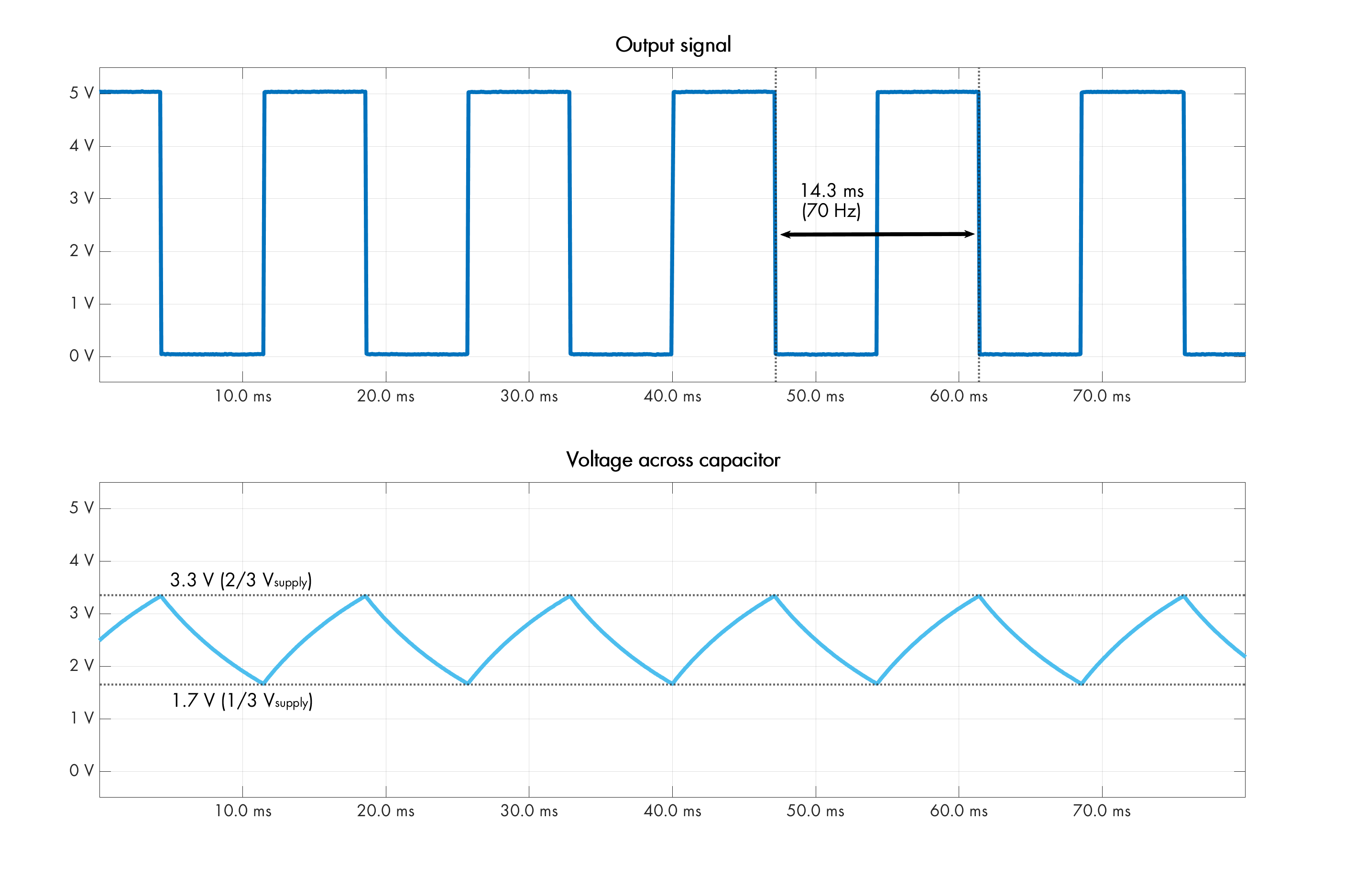
The observed frequency is about 7% lower than predicted: 70 instead of 75 Hz. Although I could pin this on component tolerances, a more honest explanation is that at Δv ≈ 1.67 V, the constant-current approximation of the capacitor charging process is stretched thin; the segments in the bottom oscilloscope trace diverge quite a bit from a straight line. Not to worry; to reduce Δv, we just need to bump up the value of R3. If we switch to 47 kΩ and keep everything else the same, the delta will be about 480 mV and the model we’re relying on will give a more precise result.
If you’re interested in a general formula to find the circuit’s operating frequency, it helps to assume that R1 and R2 are the same. If so, we can replace them with a new composite resistor with half the resistance and solve the standard voltage divider equation to find out what would happen if the feedback signal moves from 0 V to Vsupply:
With two identical resistors, the capacitor waveform is centered around ½ Vsupply, so the formula for the average current is also pretty simple (and doesn’t change between the charge and discharge periods):
This gives us all we need to solve for frequency using the capacitor equation, rewritten as t = Δv · C/I:
This further simplifies to:
…and in the specific case of R1 = R2 = 10 kΩ plus R3 = 47 kΩ, we get:
The method outlined earlier on is not the only conceptual approach to build oscillators. Another way is to produce resonance. We can do this by taking a standard op-amp voltage follower which uses negative feedback to control the output — and then mess with the feedback loop in a particular way.

In the basic voltage follower configuration, the op-amp reaches a stable equilibrium when Vin+ ≈ Vin- ≈ Vout. Again, the circuit works only because of the negative feedback loop; in its absence, Vin- would diverge from Vin+ and the output voltage would swing toward one of the supply rails.
To turn this circuit into an oscillator, we can build a feedback loop that normally provides negative feedback, but that inverts the waveform at a particular sine-wave frequency. This turns negative feedback into positive feedback; instead of stabilizing the output voltage, it produces increasing swings, but only at the frequency at which the inversion takes place.
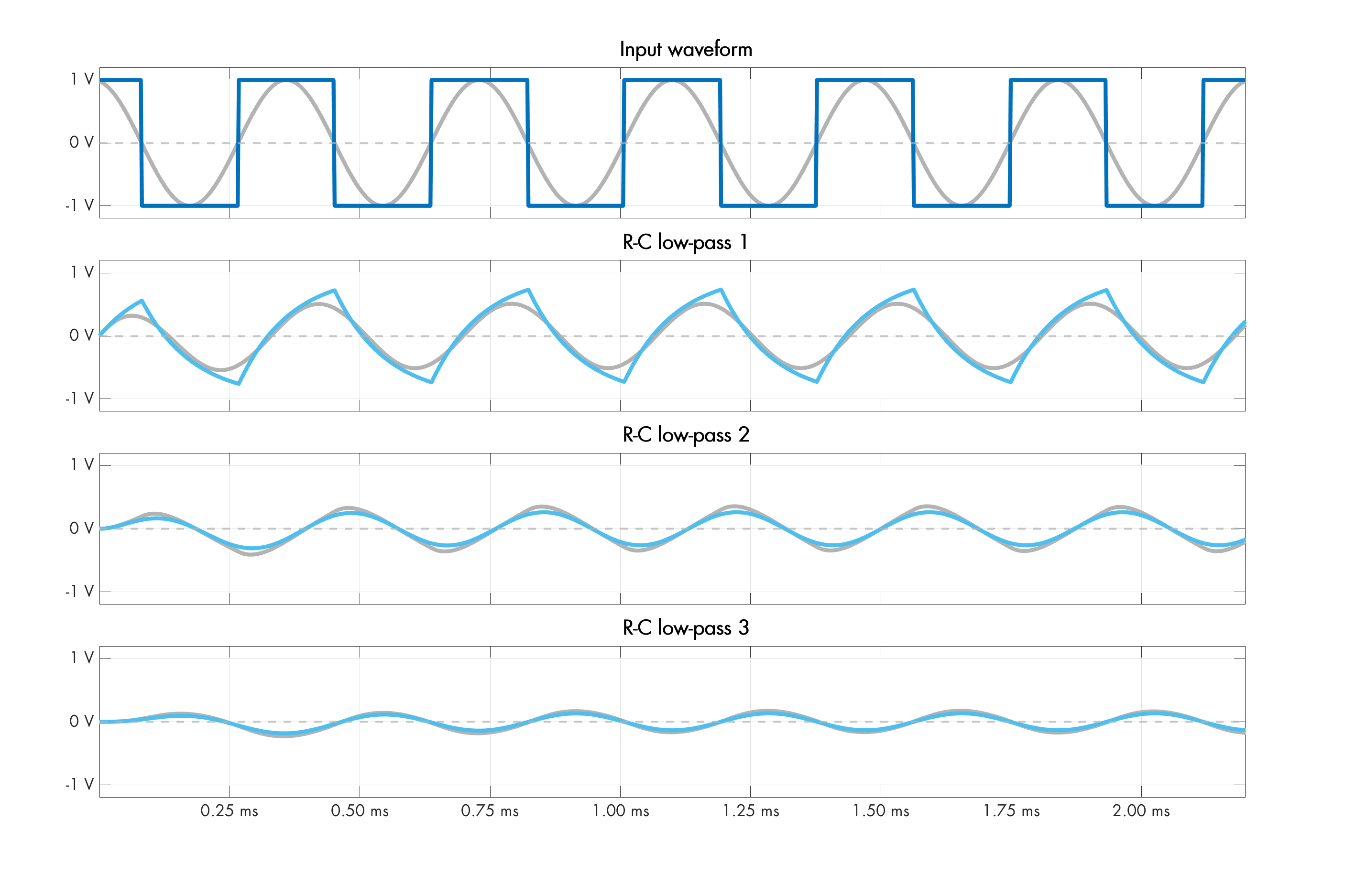
Such a selective waveform inversion sounds complicated, but we can achieve it a familiar building block: an R-C lowpass filter. The mechanics of these filters are discussed in this article; in a nutshell, the arrangement produces a frequency-dependent phase shift of 0° (at DC) to -90° (as the frequency approaches infinity). If we cascade a couple of these R-C stages, we can achieve a -180° phase shift at some chosen frequency, which is the same as flipping the waveform.
A minimalistic but well-behaved op-amp solution is shown below:
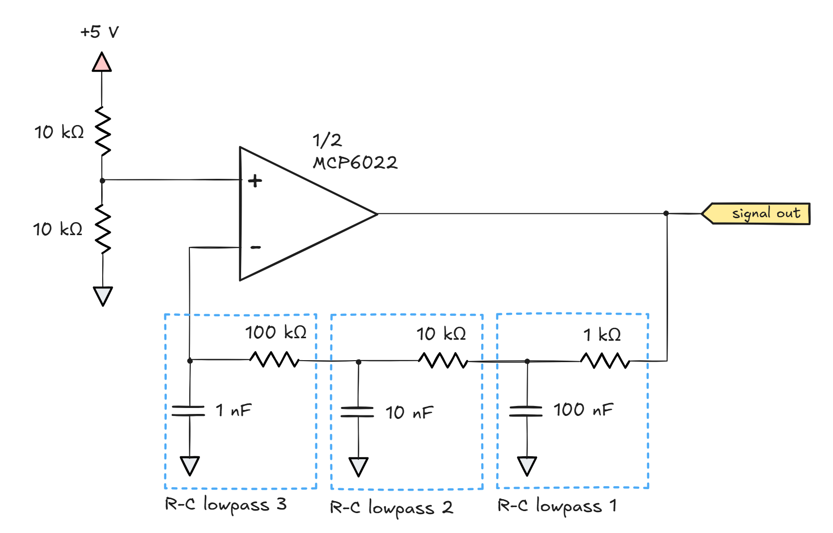
In this particular circuit, an overall -180° shift happens when each of the R-C stages adds its own -60°. It’s easy to find the frequency at which this occurs. In the aforementioned article on signal filtering, we came up with the following formula describing the shift associated with the filter:
Arctangent is the inverse of the tangent function. In a right triangle, the tangent function describes the ratio of lengths of the opposite to the adjacent for a particular angle; the arctangent goes the other way round, giving us an angle for a particular ratio. In other words, if x = tan(α) then α = arctan(x). This allows us to rewrite the equation as:
We’re trying to solve for f at which θ = -60°; the value of -tan(-60°) is roughly 1.73, so we can plug that into the equation and then move everything except f to the right. Throwing in the component values for the first R-C stage in the schematic, we obtain:
You’ll notice that the result is the same for the other two stages: they have higher resistances but proportionally lower capacitances, so the denominator of the fraction doesn’t change.
Oscilloscope traces for the circuit are shown below:
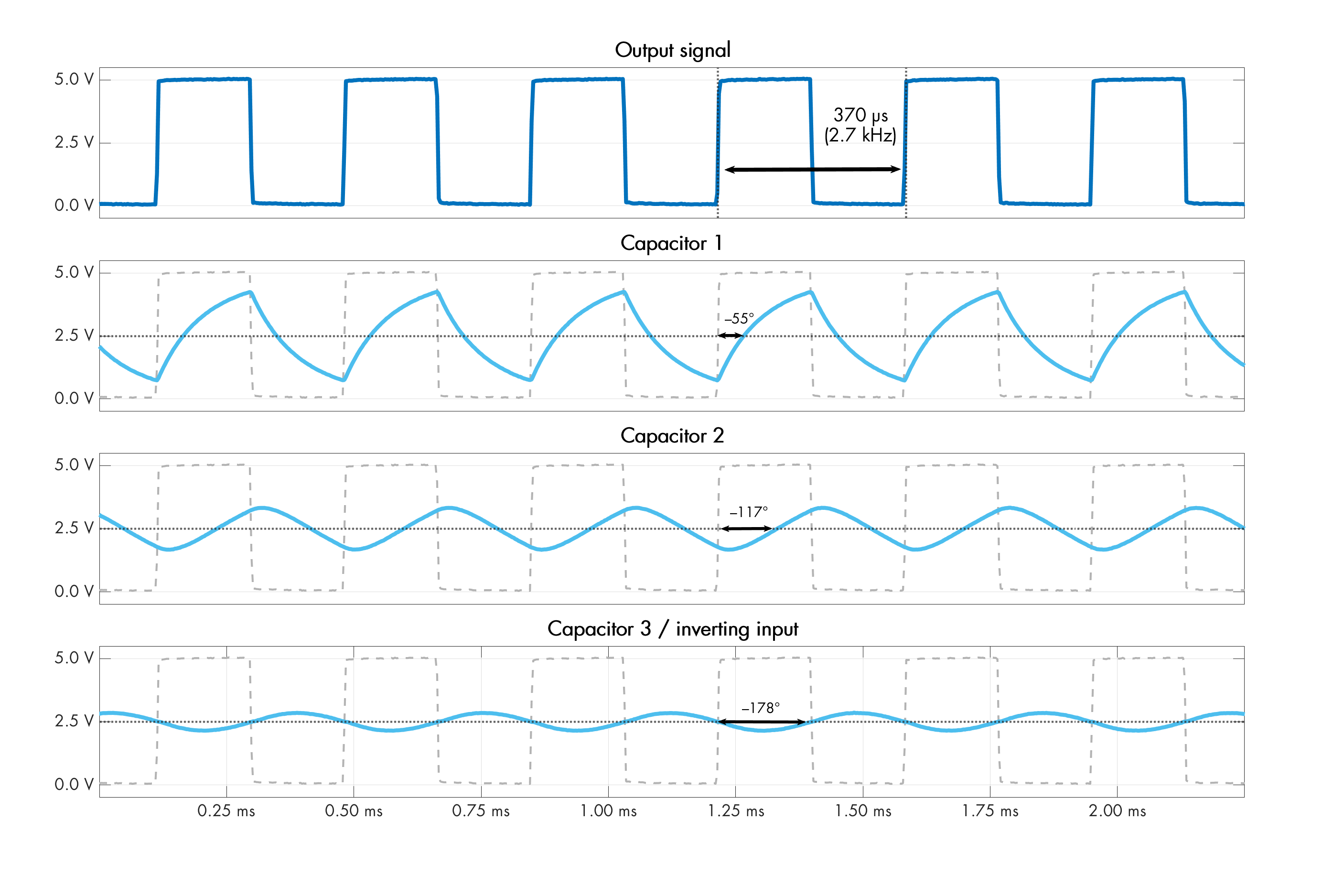
Because the amplifier’s gain isn’t constrained in any way, the output waveform is a square wave. Nevertheless, in a lowpass circuit with these characteristics, the resulting waveforms are close enough to sinusoids that the sine-wave model approximates the behavior nearly perfectly. We can run a discrete-time simulation to show that the sine-wave behavior of these three R-C stages (gray) aligns pretty well with the square-wave case (blue):
To make the output a sine wave, it’s possible to tinker with with the feedback loop to lower the circuit’s gain, but it’s hard to get it right; insufficient gain prevents oscillation while excess gain produces distortion. A simpler trick is to tap into the signal on the non-inverting leg (bottom oscilloscope trace) and use the other part of a dual op-amp IC to amplify this signal to your heart’s desire.
Some readers might be wondering why I designed the stages so that each of them has an impedance ten times larger than the stage before it. This is to prevent the filters from appreciably loading each other. If all the impedances were in the same ballpark, the middle filter could source currents from the left as easily as it could from the right. In that situation, finding the point of -180° phase shift with decent accuracy would require calculating the transfer function for the entire six-component Franken-filter; the task is doable but — to use a mathematical term — rather unpleasant.
Footnote: in the literature, the circuit is more often constructed using highpass stages and a discrete transistor as an amplifier. I’d wager that most authors who present the discrete-transistor solution have not actually tried it in practice; otherwise, they would have found it to be quite finicky. The version presented in this article is discussed here.
If you enjoyed the content, please subscribe. I’m not selling anything; it’s just a good way to stay in touch with the writers you like.
Read the original article
Comments
By ErroneousBosh 2025-11-2110:374 reply > There’s an old electronics joke that if you want to build an oscillator, you should try building an amplifier
It's funny, I was just thinking this morning about an old article in (I think) Television magazine that I read in the 80s when I was getting into electronics. The author was talking about some service notes he'd received for a particular model of Philips radio, which had just come out, and it was when shops tended to have their own service department that would repair things right there in the shop - and also, apply any "factory fixes".
One such fix was described as "Fix VIUPS", and involved changing a couple of resistors and adding a couple of capacitors. Not really any difference, but the author did think it seemed to make the amp a bit more stable and less inclined to make squealy ploppy noises at high volume when the battery was low. But, curiosity got the better of him, so he rang the Philips rep - what's this "VIUPS"?
No idea. But I'll get hold of someone at head office you can ring. Okay, what's this "VIUPS" thing? No idea, said the head office guy, but I can put you in touch with one of the factory engineers in Eindhoven.
So, a call came in, an international call! Quite a big deal in the 80s. "What's this VIUPS Fix thing in the service notes?" he asked the guy.
"Aha yes", he said in a heavy Dutch accent, "the VIUPS is the noise the set makes when the fault is present."
VIUPS VIUPS VIUPS. Yup.
> There’s an old electronics joke that if you want to build an oscillator, you should try building an amplifier
The way I heard it was "amplifiers oscillate and oscillators don't".
By dbcurtis 2025-11-2116:37 The way I've heard it is: Being a microwave engineer is the easiest job in world. You basically only do two things, design oscillators and design amplifiers. What's the worst thing that can happen to an amplifier? It oscillates! And what's the worst thing that can happen to an oscillator? It won't start, but it's usually still a pretty good amplifier. Win-win!
By B1FF_PSUVM 2025-11-2122:52 "The fears of a designer are amplifiers that oscillate and oscillators that don't."
> There’s an old electronics joke that if you want to build an oscillator, you should try building an amplifier
The most easy way to annoy a neighbor using AM radios, it's using a regenerative AM receptor with too high gain. Could oscillate and begin to emit noise at the same freq that are you tuning. Adding a simple carbon microphone to it, and setting the gain to the max, was a very easy way of building a AM radio emitter.
By IAmBroom 2025-11-2113:57 Pretty sure just blasting that rock and roll "music" out the window is easier.
Damn hippies.
By ErroneousBosh 2025-11-2122:15 I once made a guitar amp that oscillated pretty well at around 100MHz, sufficient to wipe out one of the FM radio stations for about half a mile radius.
By severak_cz 2025-11-2122:291 reply > There’s an old electronics joke that if you want to build an oscillator, you should try building an amplifier
This can be easily demonstrated using so called no-input technique[0] which basically means that you patch audio mixer output to it's input and it starts feedbacking and you can create some tones from this. Note that this needs to be done carefully.
By lioeters 2025-11-2215:55 That was a delicious sonic experience. Reminds me of "circuit bending", an aesthetic technique to push the limits of hardware in unintended ways to get creative effects. Otherworldly sounds emerging from glitches, feedbacks, overdrives.
What's fascinating is the endless variety of chaos and patterns created from such a simple mechanism and system. It seems the feedback is key, how an output is fed back into another input. Recursive functions, like fractal geometry.
By nullorempty 2025-11-2117:38 Yea, that resonates!
It's super easy to build LC oscillator.
I made a program that generate random topology and uses spice simulation to find if it oscillate. The goal was to find some novel LC oscillators. It worked, it found many different oscillators. I let it ran for a while and soon I found out that the simplest possible LC oscillator has 1 inductor, 2 capacitors, 1 resistor and 1 transistor. I found many different variations of it, I called this class of oscillators "LCCRT oscillator" and it also always had 2 internal nodes so that's not very large search space (40000 combinations) so I generated all possible combinations and I found out there are exactly 12 distinct LCCRT topologies.
Basically any time cap connects to a rail it can be placed to other rail as well, and any time one rail connects via resistor, the resistor can also be moved to other rail. This creates 12 possible combinations. I tested them in real life and they are stable, even used one in metal detector.
Of course it found many different topologies. Some times they were unique, other times they could be simplified into already found oscillator. It can also use multiple transistors not just one. You can find entire project on github, it is a ngspicejs script: https://github.com/dvhx/lc-oscillator-finder
"Novel". Those are all Collpits LC oscillator variants, circa 1918. All LC oscillator topologies were thoroughly investigated more than a century ago, hundreds of books have been written about them. A little more humility please
Passive circuits have been novel for a long time now, or at least very very quaint. It is hard to put much stock in a coil when it is banal to walk around with 100 billion transistors in your pocket.
One of my favorite books is Tremaine's Passive Audio Network Design, seems appropriate right now. Passive circuit design is great fun and a lost art.
By ofalkaed 2025-11-2121:41 Novel is considerably more complex than just new and even new is more nuanced; your new car could be as old as the Colpitts oscillator. Novel carries with it the unfamiliar and how that unfamiliarity alters our perception of what was once familiar. When you drive about in your new Model T everything is different, you are sitting considerably higher than you do in your old 240Z that you have driven since 1973 and its vertical windshield gives a far more limited view, its lack of power steering makes you aware of how sharp those curves in the road are and everyone notices you when you drive by. Then you take you old Datsun on a milk run and now it is more familiar than it was, you are aware of how intimately you respond to it and it responds to you but also of how its power steering removes some of the intimacy of driving and people stop talking to you about what you are driving because you have been driving that car since 1973 and everyone knows you as the person who has driven the same car since 1973, they ask you how your day is instead of complimenting your antique car. But the novelty eventually wears off and the old Model T becomes as familiar as your 240z.
Most in electronics never learn to drive without power steering, they view passive circuits as simple little things that need active components between them so they don't interact with each other in maddening ways but those interactions are not maddening once you understand them and learn to exploit them.
I don't think anyone used novel to mean rare.
By seg_lol 2025-11-233:20 Hey, we try and keep it a little bit more "lol" around here.
As a CS guy who got the absolute bare minimum introduction to electronics: why isn't the article about LC oscillators?
I get the impression that there was some requirement to use transistors that I was missing. The article briefly mentions some kind of inductor as a rare component.
By the__alchemist 2025-11-2115:28 Hah! As an IC baby, I assumed it would be about what goes on inside crystal oscillators, TCXOs, MEMS oscillators, the difference between the one that you add 2 caps to with in and out vs the ones that don't need In and use a single bypass cap.
By tlb 2025-11-2121:15 Inductors (the L of LC) are large and expensive except at very high frequencies. So audio circuits are normally designed with just resistors and capacitors.
And you always need an active component like a transistor. A pure LC can oscillate for hundreds of cycles but not indefinitely.
By amelius 2025-11-219:38 Nice! Perhaps you could sort them based on Q-factor.
By achr2 2025-11-2116:52 This is really great, both from a specific application perspective, but also the approach. Really enjoyed looking through the repo and was inspired by your work.
By webdevver 2025-11-2110:09 this is always the risk of posting on hackernews: a random commentator absolutely iq mogs the op.
When I was starting out in electronics I found the easiest way to build an oscillator was to build an amplifier and the easiest way to build an amplifier was to build an oscillator. I guess the trick is to be 7 years old and have far more ambition than skill. Couldn't guess at how many tries it took me to make an amplifier that didn't oscillate and when I moved onto oscillators, they never oscillated but they did amplify. In that first year or so, I couldn't actually read resistor color codes, but I thought I could.
If you combine a 3 year-old, whose favorite word is "why?", and the ambition of a 7 year-old you might just end up with the most productive genius possible.
By IAmBroom 2025-11-2115:19 Add the social insecurity of a pubescent, and you suddenly have a madman knowitall (with almost no actual knowledge) that slows that learning to a drip.
It's a miracle high schools are able to achieve anything, really.
By dtgriscom 2025-11-221:19 And, in some circumstances, they'll oscillate.
> the trick is to be 7 years old and have far more ambition than skill
Never lose this
Apologies for my bluntness, but in my humble opinion, American society would be better if it had fewer adults like this.
By JKCalhoun 2025-11-2113:02 You are likely talking about a different aspect of child-mindedness than the person you were responding to.
By ofalkaed 2025-11-2110:18 Being able to enjoy and find worth in the process regardless of the outcome is bad? Are we man-children if we don't treat everything as if it were as serious as cancer? I'm not really sure what you are trying to say.
Ambition develops skill. One of the problems with American society is people thinking they have skill when they don't. If people knew they had ambition and no skill, they'd try things and learn.
By majorchord 2025-11-2114:44 Dunning-Kruger actually applies to everyone, especially to people who openly and over-generalizingly criticize an entire nation's supposed lack of skill.
By taneq 2025-11-2111:43 I think the scenario of childlike wonder and limitless ambition is a little different to the scenario of embraced ignorance and wilful misrepresentation of any surviving facts in furtherance of the agenda du jour.
By HeyLaughingBoy 2025-11-2121:51 Ambition should always outpace skill. Otherwise, how would we get anywhere?
By hollerith 2025-11-2114:54 Only because I don't know the rest of the world well enough to say.
By jacquesm 2025-11-2112:01 Yes, but then again, we could make a very similar comment about Hackernews.
that's a helluva thing to just drop. What are your priors? Are you American yourself, or living in or near it? In what way would it be better? How so?
By hollerith 2025-11-2117:31 Yes, American citizen living in the SF Bay Area.
By fuzzfactor 2025-11-2114:44 Wait until you see what some of the people in other countries do when they try to imitate Americans.
It makes you think, why even bother?
Not my downvote BTW.
Often the biggest thing holding you back from doing something is the sensible, mature understanding that it’s impossible.
By dylan604 2025-11-2116:52 Growing up, I never had the budget of a real TV studio, but had equipment that would approximate a real TV studio. I would come up with ways to recreate what they were doing because it could clearly be done, but by using totally different equipment that only looked like it was up for the task. Asking the real TV people if it could be done, they'd say no. I'd say hide and watch (too young to have a beer to ask them to hold).
Sometimes, the box a degree stuffs you into with all of that learning often means losing some creative out-of-the-box thinking abilities. I get away with things all the time because I didn't know you weren't supposed to not do this, yet now that I have, it works just fine.
