
How fast can RP2350 really go? Mike starts his Christmas holidays with a deep dive into Pico 2 overclocking, with the assistance of a seasonally appropriate amount of dry ice ❄️ A couple of years ago…
How fast can RP2350 really go? Mike starts his Christmas holidays with a deep dive into Pico 2 overclocking, with the assistance of a seasonally appropriate amount of dry ice ❄️
A couple of years ago Raspberry Pi posted about overclocking a regular Pico to a ridiculous degree - achieving a 1 GHz overclock and (briefly) boosting the performance of the Pico above the original Pi.
Picos overclock very well, and the original Raspberry Pi Pico will normally run at over 400MHz if given a 1.3V core voltage. On the RP2040 that is as far as you can easily go because the on-board voltage regulator is limited to supplying a maximum of 1.3V.
When I first got my hands on the RP2350 datasheet, one thing I noticed rather quickly was that the voltage regulator could have the voltage limit disabled, so that voltages above 1.3V could be requested. And once I got a Pico 2, I was intrigued to see how it would behave at higher core voltage (and whether the magic smoke would come out if I raised the voltage too high!)
Initial experiments
Using this MicroPython script I was able to request different voltages from the regulator. To find out how fast the RP2350 would clock at a given voltage I ran a simple test that computed 100 factorial and checked the answer was correct, and then incremented the clock speed and continued until it stopped working.
I then did a more rigorous test using the MicroPython performance benchmark to find out whether things were stable. Generally I had to back off the CPU clock by 20MHz or so in order for the performance benchmark to run multiple times cleanly, compared to how fast it would pass the very simple 100! test. I live bleated (that's what we're calling Bluesky posts for now) my experimentation and some details about the RP2350 as I was doing this.
Voltage, max stable clock speed and temperature for those initial tests was as follows:
| Voltage | Max Clock | Temperature |
|---|---|---|
| 1.1 V | 312 MHz | 25.6 C |
| 1.3 V | 420 MHz | 33.6 C |
| 1.5 V | 512 MHz | 44.4 C |
| 1.7 V | 570 MHz | 53.7 C |
This was the first time I'd really felt an RP2 chip getting hot - RP2040s running at 400 MHz or so and 1.3V only get a little warm.
Adding some cooling
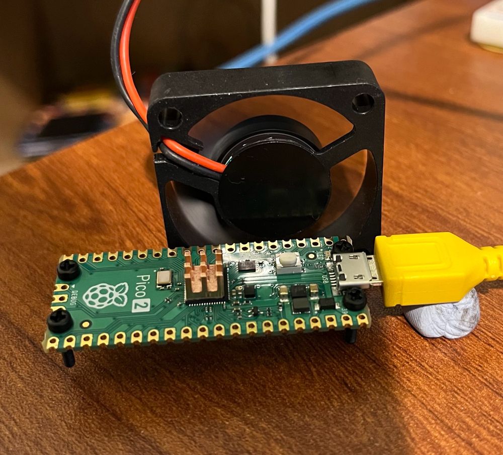
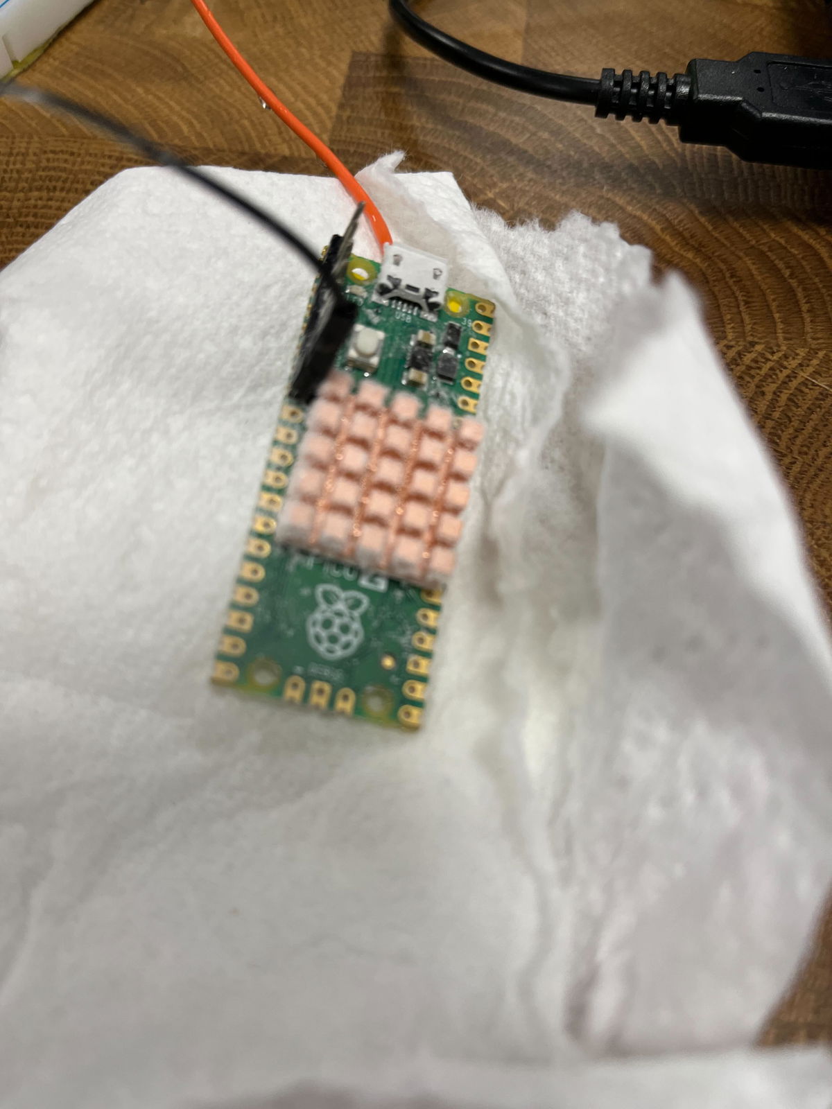
To combat the heat issue I added a tiny heatsink to the RP2350 on the Pico 2, and set up a small PC fan pointing at it to give good airflow. I again live bleated the experiment, pushing the RP2350 to higher voltages and clock speeds:
| Voltage | Max Clock | Temperature |
|---|---|---|
| 1.7 V | 576 MHz | 35.0 C |
| 1.9 V | 636 MHz | 41.1 C |
| 2.0 V | 654 MHz | 44.8 C |
| 2.2 V* | 678 MHz | 57.5 C |
I'll admit that I was rather concerned going above 2.0V - while the on board regulator provides 0.05V or 0.1V increments up to 2.0V, the next step up from 2.0V is 2.35V. This seemed like it was getting a long way above the stock 1.1V core voltage, and I thought the danger of cooking the RP2350 was rising.
However, it turned out the performance gain from 2.0 to 2.35V wasn't as much as would be expected, and on further investigation the voltage that the voltage regulator was supplying didn't actually make it above about 2.2V - the on board regulator isn't able to provide enough current to run the RP2350 at these high voltages.
Test Point 7
So, how did I find out that the supplied voltage wasn't as high as requested? It turns out the Pico 2, rather handily, has a test point on the back that allows you to measure the core voltage. It was therefore very easy to probe it with my multimeter and see the voltage being delivered didn't match up to the requested voltage.
But if you can probe the voltage here, it would also be straightforward to inject a voltage externally. That would mean we could use a bench power supply to provide as much voltage and current as the Pico 2 could take!
Taking it further
A plan forms
I'd been chatting to the folks at Pimoroni about these experiments, whilst helping them with the Presto firmware and other bits and pieces. Niko from the Pimoroni team suggested, perhaps jokingly, that we should try a Liquid Nitrogen overclock.
I'd arranged to pop in to visit Pimoroni HQ at the start of my Christmas break, so we wondered if it might be possible to give this a try. However, LN2 is a little tricky to handle and not totally straightforward to acquire. I was also worried that we could have problems with the soldering, PCB or connections to the Pico cracking under the extreme cold of LN2.
Solid CO2 (AKA dry ice) on the other hand, is relatively easy to acquire and requires only fairly basic safety precautions. It should allow cooling of the Pico 2 to around -80C, which seemed like it would be enough to give a decent speed boost. Niko ordered some dry ice and the plan was set.
⚠️ (Editorial note: do not experiment with solid CO2 / dry ice unless you know what you're doing, have considered the problems that carbon dioxide sublimation and things being cooled to -80C can cause and have taken appropriate safety precautions!)
Test setup
I wanted to make sure we were pretty rigorous about the testing - unlike the earlier experiments using the MicroPython performance benchmark, I wanted to get both cores running flat out. Therefore I decided to use the freely available CoreMark benchmark as the test, as this would report result comparable to other CPUs, and it would check for correct operation and report errors if there were problems.
I also wanted the option of running the Pico from the ring oscillator, as described in the Raspberry Pi article linked at the top. Additionally, we weren't quite sure whether the crystal oscillator frequency might be changed by very low temperatures. Therefore, to measure time accurately I sent a 1MHz clock into the Pico 2 under test, and used a simple PIO program to count the cycles. This allowed us to run from the ring oscillator or crystal, and get accurate benchmark results measured using a known good clock.
I also made some other adaptations to Protik Banerji's version of Coremark for RP2040, to:
- Compile for RP2350, and get two core operation working
- Use a copy to RAM build so we got maximum performance and didn't need to worry about the flash clock divider
- Use UART output rather than a USB console to avoid USB interrupts slowing down the test, and make it easier to recover from the RP2350 crashing.
- Print the temperature from the RP2350's on board temperature sensor after each run
- Run repeatedly in a loop instead of just once
- Add a prompt before the runs start to allow the voltage to be set (or the on board regulator to be disabled), and the frequency to be set or the ring oscillator to be selected
- Add a check for console input after each run, allowing the configuration to be modified, or the pico to be rebooted into DFU mode without having to hit the BOOTSEL button. The latter meant we could update things even if it was difficult to press that button when it was buried in dry ice.
I used a version of Álvaro Fernández Rojas' pico-uart-bridge on a Pico W to communicate with the Pico 2 under test. This was modified to provide the 1 MHz reference clock, and also look for lines starting "Temp" or "CoreMark" and send them over WiFi.
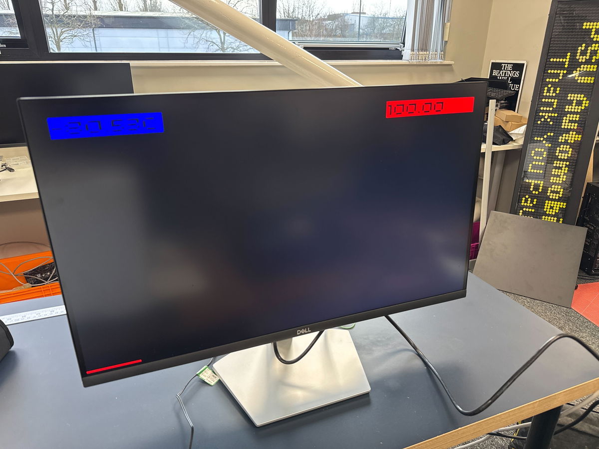
Using MicroPython on a PicoVision, and a modified version of the temperature display example, I read the temperature and CoreMark readings from the Pico W and graphed them on a monitor, so we could see what was happening while running the tests (I wrote this part in traditional hacker style entirely in my hotel room the night before going into Pimoroni HQ, using the dodgy hotel WiFi and the TV in the room to test it!)
Getting set up
First up we needed to get all three Picos involved in the setup, and the surrounding hardware working and verified. At first we had some problems with the WiFi communication, which wasn't implemented in the most reliable way, but that seemed to settle down after some initial hiccups.
We got the test Pico 2 running at 100MHz to establish a baseline. Jon at Pimoroni also pointed out that to make things easier to read it would be better to report a number in MHz instead of the CoreMark score, this was achieved simply by taking the ratio of the CoreMark score at 100MHz to the CoreMark being reported. As the CoreMark was running from internal RAM the score should be entirely linear with frequency.
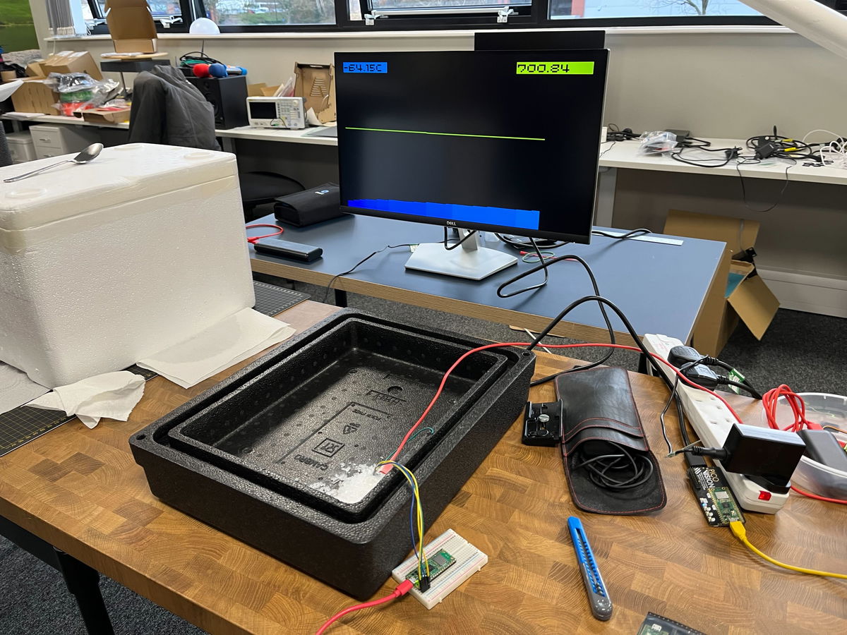
Let's cool the Pico 2!
Next up we got the Pico 2 I'd been using for all the testing so far, complete with its tiny heatsink, and covered it in dry ice.
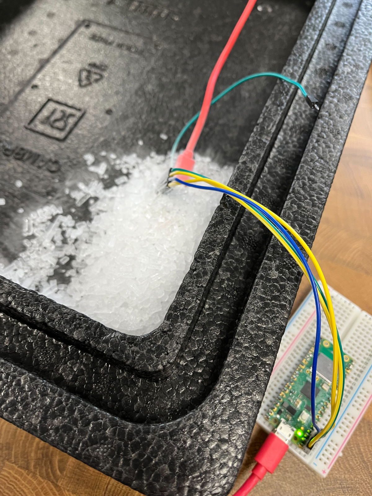
We did some initial testing using the internal voltage regulator, and got it stable at 700MHz with ease:
Let's cook the Pico 2!
We wanted to push up to see where the limits were, so we wired up a power supply to test point 7, disabled the onboard voltage regulator and nervously increased the voltage above the maximum of 2.2 V that I had managed before.
Up and up the voltage went, and while we got diminishing returns on the frequency acheivable, the magic smoke stayed inside the chip!
Here we got to 800MHz at 2.8V:
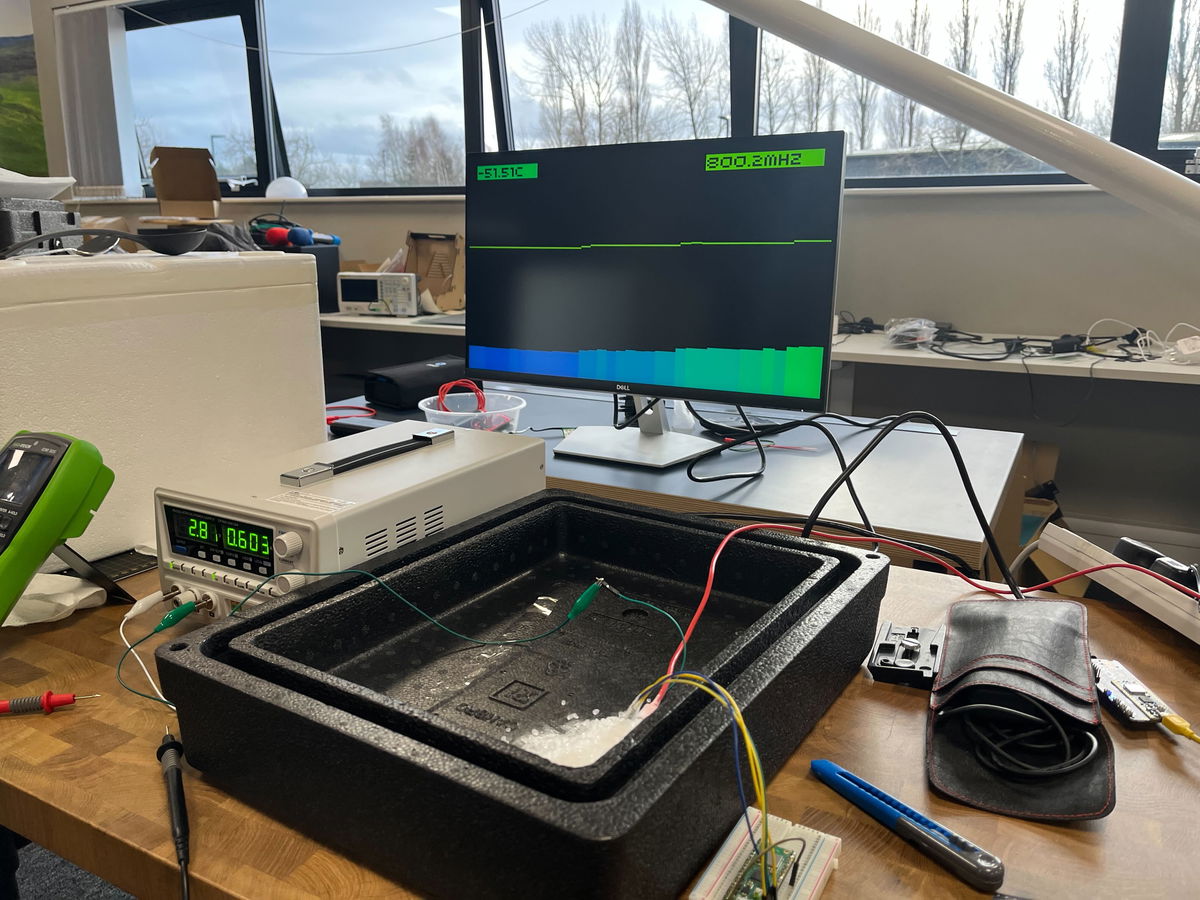
We realised our setup here was not ideal, as the ground for the core voltage was going via the Pico W. We measured the voltage at the Pico in the dry ice and it was around 200mV lower than the voltage being supplied, due to the resistance through that long path. With that in mind we pushed the voltage up to 3.3V and even a little higher, but it didn't allow that much more speed - the fastest we got to was 840MHz and that wasn't stable for long, we think due to the RP2350 heating up while drawing around 1A of current!
Despite this abuse the Pico 2 still works just fine!
Ring oscillator experiments
The RP2350 datasheet suggests you can "automatically overclock" using the ring oscillator - the concept is that because the ring oscillator itself changes frequency in line with the core voltage and temperature of the chip, the same ring oscillator setting should be stable across all conditions. This appears very much not to be the case (at least while using the Arm cores - see later).
I had found that (air cooled) using the "TOOHIGH" setting and maximum drive strength the Pico 2 ran ok up to around 1.5V and then failed, with the observed frequency at lower voltages being lower than the maximum that could be run from the crystal oscillator, but then it going up past the maximum frequency as the voltage increased. I'm not sure why this is. Using a drive strength one notch less for one of the two stages had it stable up to the maximum I had tested air cooled, so this was the initial setting we tried using.
However, as we got the voltage higher, at around 2.6V again the RP2350 would crash when running from the ring oscillator, we tried backing off the drive strength which helped a bit, but ultimately it was difficult to find a setting that would run stably at the highest voltages, while being close to the frequency we'd managed with the crystal. That was a bit unfortunate, given that at frequencies above 800MHz we could only step the frequency from the crystal in increments of 12MHz.
Finding a better Pico 2
The Pico 2 that we were using was just the first one I had bought, with no selection based on whether it was a particularly good one for overclocking. Pimoroni rustled up 7 potential victims Pico 2s for me to test to try and find one that might overclock the best.
I quickly ran the Micropython frequency search test (linked near the top) on all of them, finding that at 1.1V they would max out at between 316 and 336MHz. Mark from Pimoroni soldered up the two best ones for further testing. We soldered a few more pins this time to get access to another ground, so the core voltage supply didn't go via the Pico W.
How fast can we go?
Despite being the fastest at 1.1V, the first Pico 2 we tested wasn't that much better than the initial one. We were briefly able to run it at 850MHz at 3.05V, but it wasn't stable. (This is 850MHz measured by dividing the CoreMark, we requested 852MHz but it seems got slightly less due to the crystal being cold or some other effects of the high core voltage). Going higher than 3.05V seemed to actually make it less stable, so this seemed to be the limit. At 840MHz requested frequency it ran for a couple of minutes, but we saw errors reported from the CoreMark so there must have been errors running some instructions.
Thinking that a lot of the problem in getting faster was just the chip warming up too fast, we looked for a larger thermal mass to try and keep it cooler for longer. Paul produced a big chunk of copper, significantly larger than the Pico 2 itself, which seemed promising.
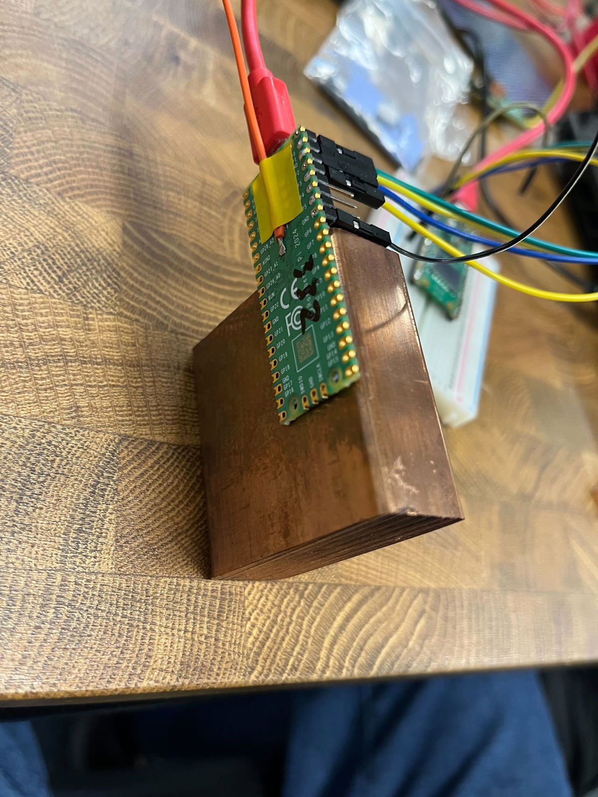
We tried attaching this to the Pico 2 with a couple of thermal pads, but it seems they didn't provide great thermal conductivity at these low temperatures, because the results were actually worse with this than without any heatsink at all! That was a shame - maybe we should have tried just getting direct contact of the copper on top of the chip, but we were worried about shorts.
We switched over to the other Pico 2 and attached a heatsink designed for the BCM2712 on the Pi 5 to it. That got better results - obviously the simple test at 1.1V room temperature doesn't account for everything! This one would briefly manage 864MHz requested (reported 860.7MHz), and would run stable at 840MHz for some time, with no errors. The best so far!
Testing the RISC-V cores
The RP2350 is an interesting chip, with two RISC-V cores in addition to the two more established ARM cores. Mark had reminded me that we should try the RISC-V cores for comparison, and I got the image built for them - this is pretty simple to do, you just need to install the RISC-V version of gcc and change the PICO_PLATFORM setting to rp2350-riscv.
I found that CoreMark actually gave a slightly higher performance per MHz using the RISC-V cores - just under 5% faster. So if you have an integer-only use for the RP2350 it is definitely worth checking if the RISC-V cores might give better performance!
Adjusting the PicoVision monitor for the CoreMark per MHz, we got the same Pico 2 running again.
Maximum speed
Ramping the voltage up again running off the ring oscillator, with the drive strength one notch off maximum on one of the two stages, this time we found it didn't crash as the voltage increased, until we got to around 3.0V. That meant that at around 2.95V we had a stable overclock of 820-840MHz running off the ring oscillator (with the fluctuation in frequency due to temperature).
Switching over to the crystal, with 3.05V we got 861.6MHz (864MHz requested) running cleanly, and it even ran for nearly a minute at 873.5MHz before crashing. We had no luck trying to get a requested frequency of 888MHz to run.
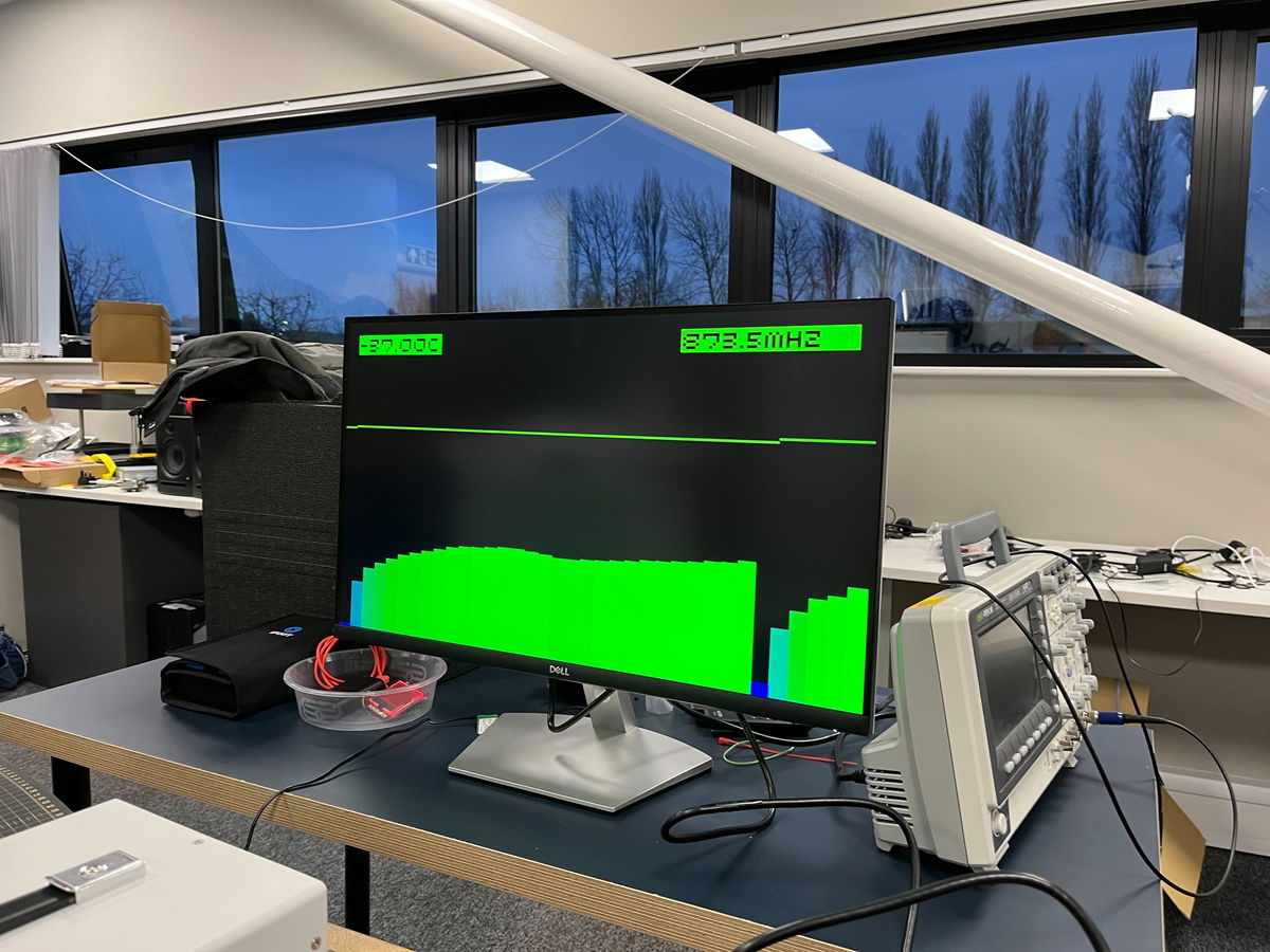
So the top speed we managed was 873.5MHz, though when we tried this again the Pico refused to start at 3.05V, so I guess we were beginning to cause some damage with the high voltage.
For a final test we left it running on the ring oscillator at 2.95V, and it ran for around 10 minutes before we let it get a little too warm (up to around -20C).
Conclusions
Firstly, the RP2350 and Pico 2 is incredibly hardy. Despite the cold temperatures, some accidental shorting due to moisture when running it while cooling and extremely high core voltages, none of the 3 Pico 2s we were playing with are dead - and I don't think there's any way you would be able to tell that they had been through this treatment.
Above 700MHz the extra performance you get ramping up the voltage gives diminishing returns. This maybe because we just weren't able to keep the chip cool enough - just packing dry ice around it, it becomes difficult to carry enough heat away. Liquid nitrogen might be interesting to experiment with to go further.
Given this experimentation, it seems around 1.6V from the voltage regulator should easily allow a 500MHz or slightly faster overclock without needing any additional cooling and likely without really causing much damage to the Pico - it might be interesting to run a Pico 2 loaded like that for a few days and see if anything bad happens.
Playing with dry ice is fun! If we get a chance to do this again we should also try overclocking a Pi 5, and see if we could get a speed record there. Although that could be rather more expensive - the great thing about using Pico 2 for this, is that at under £5 per board you can treat them with reckless abandon - after all, they each cost less than a pint of beer!
Search above to find more great tutorials and guides.
Read the original article
Comments
Great stuff.
It wouldn't be surprising if the RP2350 gets officially certified to run at something above the max supported clock at launch (150MHz), though obviously nothing close to 800MHz. That happened to the RP2040[1], which at launch nominally supported 133MHz but now it's up to 200MHz (the SDK still defaults to 125MHz for compatibility, but getting 200MHz is as simple as toggling a config flag[2]).
[1] https://www.tomshardware.com/raspberry-pi/the-raspberry-pi-p...
[2] https://github.com/raspberrypi/pico-sdk/releases/tag/2.1.1
By hnuser123456 2026-02-2017:271 reply The 300MHz, 400MHz, and 500MHz points requiring only 1.1, 1.3, and 1.5v and with only the last point getting slightly above body temperature, even with no cooling, seem like something that should maybe not be "officially" supported, but maybe mentioned somewhere in an official blog post or docs. Getting 3x+ the performance with some config changes is noteworthy. It would be interesting to run an experiment to see if there's any measurable degradation of stability or increased likelihood at failure at those settings compared to a stock unit running the same workload for the same time.
By Aurornis 2026-02-2021:08 All of their reliability testing and validation happens at the lower voltages and speeds. I doubt they'd include anything in the official docs lest they be accused of officially endorsing something that might later turn out to reduce longevity.
By londons_explore 2026-02-2014:188 reply When pushing clock speeds, things get nondeterministic...
Here is an idea for a CPU designer...
Observe that you can get way more performance (increased clock speed) or more performance per watt (lower core voltage) if you are happy to lose reliability.
Also observe that many CPU's do superscalar out of order execution, which requires having the ability to backtrack, and this is normally implemented with a queue and a 'commit' phase.
Finally, observe that verifying this commit queue is a fully parallel operation, and therefore can be checked slower and in a more power efficient way.
So, here's the idea. You run a blazing fast superscalar CPU, well past the safe clock speed limits that makes hundreds of computation or flow control mistakes per second. You have slow but parallel verification circuitry to verify the execution trace. Whenever a mistake is made, you put a pipeline bubble in the main CPU, clear the commit queue, you put in the correct result from the verification system, and continue - just like you would with a branch misprediction.
This happening a few hundred times per second will have a negligible impact on performance. (consider 100 cycles 'reset' penalty, 100*100 is a tiny fraction of 4Ghz)
The main fast CPU could also make deliberate mistakes - for example assuming floats aren't NaN, assuming division won't be by zero, etc. Trimming off rarely used logic makes the core smaller, making it easier to make it even faster or more power efficient (since wire length determines power consumption per bit).
By gibspaulding 2026-02-2020:39 I think you might like this:
You could run an LLM like this, and the temperature parameter would become an actual thing...
By boznz 2026-02-2019:49 Totally logical, especially with some sort of thermal mass, as you can throttle down the clock when quiet to cool down after, I used this concept in my first sci-fi novel where the AI was aware of its temperature for these reasons. I run my Pico2 board in my MP3 jukebox at 250Mhz, it has been on for several weeks without missing a beat (pun intended)
By tliltocatl 2026-02-2022:00 LLM are memory-bandwidth bound so higher core frequency would not help much.
By hulitu 2026-02-2015:29 > if you are happy to lose reliability.
The only problem here is that reliability is a statistical thing. You might be lucky, you might not.
How do we know if a computation is a mistake? Do we verify every computation?
If so, then:
That seems like it would slow the ultimate computation to no more than rate rate at which they can be these computations can be verified.
That makes the verifier the ultimate bottleneck, and the other (fast, expensive -- like an NHRA drag car) pipeline becomes vestigial since it can't be trusted anyway.
By moffkalast 2026-02-2018:281 reply Well the point is that verification can run in parallel, so if you can verify at 500 Mhz and have twenty of these units, you can run the core at 10 GHz. Minus of course the fixed single instruction verification time penalty, which gets more and more negligible the more parallel you go. Of course there is lots of overhead in that too, like GPUs painfully show.
Right.
So we have 20 verifiers running at 500MHz, and this stack of verifiers is trustworthy. It does reliably-good work.
We also have a single 10GHz CPU core, and this CPU core is not trustworthy. It does spotty work (hence the verifiers).
And both of these things (the stack of verifiers, the single CPU core) peak out at exactly the same computational speeds. (Because otherwise, the CPU's output can't be verified.)
Sounds great! Except I can get even better performance from this system by just skipping the 10GHz CPU core, and doing all the work on the verifiers instead.
("Even better"? Yep. Unlike that glitch-ass CPU core, the verifiers' output is trustworthy. And the verifiers accomplish this reliable work without that extra step of occasionally wasting clock cycles to get things wrong.
If we know what the right answer is, then we already know the right answer. We don't need to have Mr. Spaz compute it in parallel -- or at all.)
By firefly2000 2026-02-2020:461 reply If the workload were perfectly parallelizable, your claim would be true. However, if it has serial dependency chains, it is absolutely worth it to compute it quickly and unreliably and verify in parallel
By magicalhippo 2026-02-2022:371 reply This is exactly what speculative decoding for LLMs do, and it can yield a nice boost.
Small, hence fast, model predicts next tokens serially. Then a batch of tokens are validated by the main model in parallel. If there is a missmatch you reject the speculated token at that position and all subsequent speculated tokens, take the correct token from the main model and restart speculation from that.
If the predictions are good and the batch parallelism efficiency is high, you can get a significant boost.
By firefly2000 2026-02-2023:001 reply I have a question about what "validation" means exactly. Does this process work by having the main model compute the "probability" that it would generate the draft sequence, then probabilistically accepting the draft? Wondering if there is a better method that preserves the distribution of the main model.
By magicalhippo 2026-02-212:34 > Does this process work by having the main model compute the "probability" that it would generate the draft sequence, then probabilistically accepting the draft?
It does the generation as normal using the draft model, thus sampling from the draft model's distribution for a given prefix to get the next (speculated) token. But it then uses the draft model's distribution and the main model's distribution for the given prefix to probabilistically accept or reject the speculated token, in a way which guarantees the distribution used to sample each token is identical to that of the main model.
The paper has the details[1] in section 2.3.
The inspiration for the method was indeed speculative execution as found in CPUs.
[1]: https://arxiv.org/abs/2211.17192 Fast Inference from Transformers via Speculative Decoding
By moffkalast 2026-02-2018:49 Haha, well do you have a point there. I guess I had the P!=NP kind of verification in my head, where it's easy to check if something is right, but not as easy to compute the result. If one could make these verifiers on some kind of checksum basis or something it might still make sense, but I'm not sure if that's possible.
By ant6n 2026-02-210:05 You can verify in 100-way parallel and without dependence, but you can’t do it with general computation.
By hnuser123456 2026-02-2017:17 Side channel attacks don't stand a chance!
By Avlin67 2026-02-2018:03 you never had WHEA errors... or pll issue on cpu C state transition...
By iberator 2026-02-2122:52 Do you design CPUs by any chance?
You should build one in some logic simulator as its super interesting architecture.
I hate hobbysts 'cpus' being inside of FPGA. We should build real hardware instead.
Both the RP2040 and the RP2350 are amazing value these days with most other electronics increasing in price. Plus you can run FUZIX on them for the UNIX feel.
Mmh... I think that the LicheeRV Nano has kind of more value to it.
Around 20 bucks for the Wifi variant. 1GHz, 256MB RAM, USB OTG, GPIO and full Linux support while drawing less than 1W without any power optimizations and even supports < 15$ 2.8" LCDs out of the box.
And Rust can be compiled to be used with it...
https://github.com/scpcom/LicheeSG-Nano-Build/
Take a look at the `best-practise.md`.
It is also the base board of NanoKVM[1]
By geerlingguy 2026-02-2015:012 reply I think the ace up the sleeve is PIO; I've seen so many weird and wonderful use cases for the Pico/RP-chips enabled by this feature, that don't seem replicable on other $1-class microcontrollers.
By sandreas 2026-02-2015:19 Wow thanks, this is definetely something I have to investigate. Maybe the Sipeed Maix SDK provides something similar for the LicheeRV Nano.
I'm currently prototyping a tiny portable audio player[1] which battery life could benefit a lot from this.
I'd rather have the Linux SOC and a $0.50-$1 FPGA (Renesas ForgeFPGA, Gowin, Efinix, whatever) nearby.
By RetroTechie 2026-02-2016:282 reply Amazing value indeed!
That said: it's a bit sad there's so little (if anything) in the space between microcontrollers & feature-packed Linux capable SoC's.
I mean: these days a multi-core, 64 bit CPU & a few GB's of RAM seems to be the absolute minimum for smartphones, tablets etc, let alone desktop style work. But remember ~y2k masses of people were using single core, sub-1GHz CPU's with a few hundred MB RAM or less. And running full-featured GUI's, Quake1/2/3 & co, web surfing etc etc on that. GUI's have been done on sub-1MB RAM machines once.
Microcontrollers otoh seem to top out on ~512KB RAM. I for one would love a part with integrated: # Multi-core, but 32 bit CPU. 8+ cores cost 'nothing' in this context. # Say, 8 MB+ RAM (up to a couple hundred MB) # Simple 2D graphics, maybe a blitter, some sound hw etc # A few options for display output. Like, DisplayPort & VGA.
Read: relative low-complexity, but with the speed & power efficient integration of modern IC's. The RP2350pc goes in this direction, but just isn't (quite) there.
By moffkalast 2026-02-2018:412 reply Eh it's really not when you consider that the ESP32 exists. it has PCNT units for encoders, RMT LED drivers, 18 ADC channels instead of four, ULP coprocessor and various low power modes, not to mention wifi integrated into the SoC itself, not optional on the carrier board. And it's like half the price on top of all that. It's not even close.
The PIO units on the RP2040 are... overrated. Very hard to configure, badly documented and there's only 8 total. WS2812 control from the Pico is unreliable at best in my experience.
By vardump 2026-02-2023:51 They are just different tools; both have their uses. I wouldn't really put either above the other by default.
> And it's like half the price on top of all that. It's not even close.
A reel of 3,400 RP2350 units costs $0.80 each, while a single unit is $1.10. The RP2040 is $0.70 each in a similar size reel. Are you sure about your figures, or are you perhaps comparing development boards rather than SoCs? If you’re certain, could I have a reference for ESP32s being sold at $0.35 each (or single quantities at $0.55)?
PIO units may be tricky to configure, but they're incredibly versatile. If you aren't comfortable writing PIO code yourself, you can always rely on third-party libraries. Driving HDMI? Check. Supporting an obscure, 40-year-old protocol that nothing else handles? Check. The possibilities are endless.
I find it hard to believe the RP2040 would have any issues driving WS2812s, provided everything is correctly designed and configured. Do you have any references for that?
By tliltocatl 2026-02-2116:44 > wifi integrated into the SoC
I really wish we would stop sticking wireless in every device. The spectrum is limited and the security concerns are just not worth it. And if you try to sell it, certifying will be RPITA even in US (rightfully so!). Just had to redesign a little Modbus RTU sensor prototype for mass production, noticed the old version used BT MCU. So I immediately imagined the certification nightmare - and the sensor is deployed underwater, it's not like BT will be useful anyway. Why? Quote "but how do we update firmware without a wireless connection"… How do you update firmware on a device with RS-485 out, a puzzle indeed. In all fairness, the person who did it was by no means a professional programmer and wasn't supposed to know. But conditioning beginners to wireless on everything - that's just evil. /rant
